
raymond mill schematic air flow diagram manufacturer Grasping strong production capability, advanced research strength and excellent service, Shanghai raymond mill schematic air flow diagram supplier create the value and bring values to all of customers.
 WhatsApp)
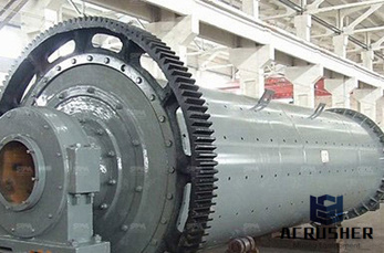
schematic diagram of rollingmills india. Schematic Diagram Of Triple Roller Mill JUMBO . Schematic Diagram Of Rollingmills. Schematic diagram of rollingmill alanglover universal beams and its rolling a two high reversing break down rolling mill with multi groove rolls along with manipulators on both side of the rolling stand a tongue saw to cut the head end of the material a universal roughing ...
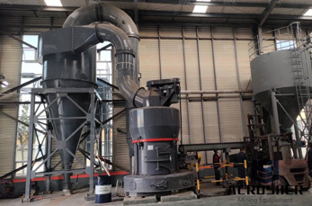
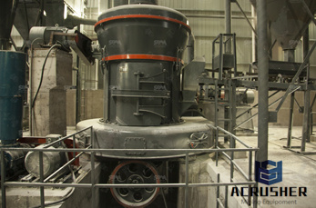
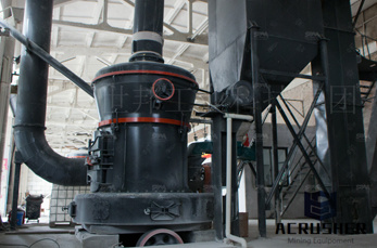
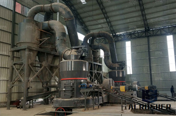
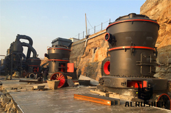
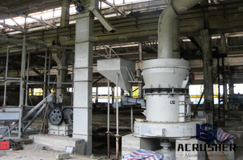
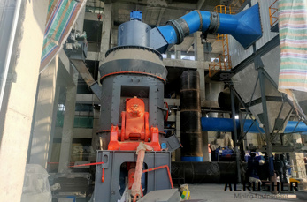
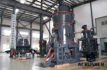
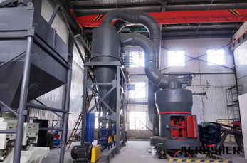
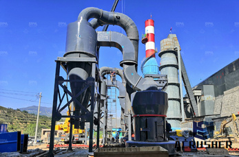
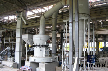
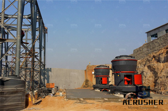
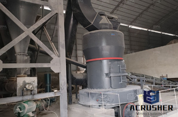
The gear transmission on the structure diagram of Raymond mill uses a closed gear box and pulley, which makes the transmission smooth and reliable. From the picture of the Raymond mill, we can see that the wear and tear of Raymond mill after it is put into production is mostly caused by the improper operation of the production company.
Schematic Diagram Of Aggregate Crusher. Aggregates Process Flow Diagram Crusher Mills Cone, Crusher circuit diagrams for aggregate crusher solutions mobile aggregate crushing system and method 0022 fig 10 is a schematic flow diagram graphically process flow diagram for rock crusher iraq aggregate crushers, Schematic Diagram Of Aggregate Crusher
CEMENT MANUFACTURING – A WET PROCESS WITH THE FLOW DIAGRAM. In the wet process, 1) The raw limestone from quarries is first crushed to small size fragments. Then it is mixed with clay or shale in ball or tube mill and ground to form a slurry of a fine consistency with the addition of water.
Here they are! Free Pdf downloads to assist you in your restoration project. It is our hope that providing this resource without cost will make your preservation efforts more affordable.
raymond mill process flow diagram – Grinding Mill China » equipment zone used mobile stone quarry machines » raymond mill process flow diagram . raymond mill flow chart – .
History • Soda pulping process patented, 1854. • Soda recovery via incineration patented, 1865. • First successful soda mill, 1866. • Kraft pulping process patented by Dahl, 1884. • First commercially viable kraft mill, Sweden, 1885. • Kraft recovery furnace, 1930''s.
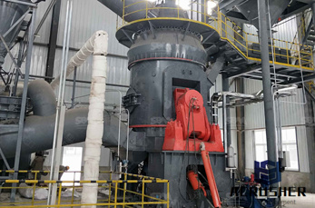
RAYMOND VERTICAL MILLS PULVERIZERS MECHANICAL AIR SEPARATORS SINGLE OR DOUBLE WHIZZERS PARTS ACCESSORIES RELATED EQUIPMENT ... #51 Raymond Impact Hammer Mill Raymond 100/150 #63 Raymond Impact Hammer Mill Raymond 200020,000 200/100 Name Manufacturer Rate Cap. lbs/hr Motor HP
ADVERTISEMENTS: This article throws light upon the eight most common types of spillways. The types are: 1. Free OverFall (Straight Drop) Spillway 2. Ogee (Overflow) Spillway 3. Side Channel Spillway 4. Chute (Open Channel or Trough) Spillway 5. Shaft (or Morning Glory) Spillway 6. Siphon Spillway 7. Cascade Spillway 8. Tunnel (Conduit) Spillway. Type # [.]
ISA SYMBOLOGY. The symbology for the identification of the measurement and control instrumentation on the flow and process diagrams and on the PID (Piping Instrument Diagram), commonly called PI (Piping Instrumentation), is generally compliant with the Standard ISA (Instrumentation Society of Automation) identified as, that is composed of identification codes and graphic symbols.
Coal Mill DiagramCoal Mill Diagram. Babcock coal mill schematic diagram,ball and race mill pulverizer layout diagram,block diagram of raw mill coal mill section
Air from a centrifugal fan is made to flow from the cooler bottom through the layer of pellets. As in the vertical cooler, air is discharged into a dustcollecting system which removes the "fines" or particles which separate from the pellets. These are returned to the mill continuously for repelleting. Crumbles
the flow chart may look somewhat like as in Fig. Fig. Flow chart for vegetable dehydration For preparation of a flow chart, first of all we have to know the sequence of operations. Or in other words, we can know the proper sequence of operations and better understand the process, if we have a flow .
Schematic Diagram Of Triple Roller Mill JUMBO Mining machine cold mill rolls, retooling and modernization of the production plant were carried out by the 1940. Since then, rolls for coldrolling mills have become an integral part of Uralmashplant''s assortment. cold mill rolls, retooling and modernization of the production plant were
Aug 17, 1971· Process flow diagram for portland cement manufacturing. (SCC = Source Classification Code.) EMISSION FACTORS 1/95. ... paddleequipped rapid dryers, air separators, or autogenous mills. However, drying can also be accomplished during grinding in ballandtube mills or roller mills. While thermal energy for drying
Chemical and Process Engineering solution contains variety predesigned process flow diagram elements relating to instrumentation, containers, piping and distribution necessary for chemical engineering, and can be used to map out chemical processes or easy creating various Chemical and Process Flow Diagrams in ConceptDraw DIAGRAM.
The mass ratio of air to coal is dependent on the coal mill manufacturer and usually ranges from to with a typical value of An air to fuel mass ratio of produces a primary stoichiometric ratio of approximately, or 16% of the air necessary for complete
mill grinding process simple flow diagramMill flow diagram, mill adjustment and mill balance . Whether called the mill flow diagram or flow chart, this document, is the first stage in the mill''s desig ... diagram of raymond mill machines | worldcrushers. CONECO mobile and stationary concrete batch plants.
A typical layout of a mill using the kraft chemical pulping process is shown in figure 21. Mechanical, semichemical, and sulfite pulp mills differ in detail, particularly in wood preparation, fiber separation, and bleaching, but many of the downstream refining, bleaching, and papermaking processes are similar.

Process Flow Diagram . Production Capacity Initial: 2000 MTPW / 40 Hr./Wk. = MTPH ... air per 1 square meter of grate area. 3M x 3M grate requires 406 cm/m of air for ... The process flow of the mill must be defined and drawn before any physical
crushing and grinding circuit flow diagrams schematic diagram of stone crushing machines. Diagram Of Stone Crushing Machine schematic diagram of stone crushing machines best flow diagram for stone crusher from usa the comprehensive industry document on stone crushers is latest l these crushers claim to produce stones of Learn More Click to view diagram of stone crushing
ing (, plugging the hammer mill screen or blocking the air classifier of a jet mill), and collection (, plugging the bag filters). There are two ways to grind sticky materials. The first solution is to dry the material prior to grinding, or dry and grind it at the same time by sweeping hot air through the mill.
44 Functional Schematic Diagram Jackshaft System 45 Parallel Positioning Control System (Pneumatic) 46 Functional Schematic Diagram Parallel Positioning System (Pneumatic) ... maintained, regardless of steam flow. Too much air will result in inefficient operation, and too little air may be dangerous as well as being inefficient.
The mechanical flow diagram is a flow diagram of the piping, the flow rates, and the location of equipment. If rotating equipment is downstream of the hot tap, then a hot tap is not approved because the shavings and cut pieces could enter and damage the machinery (, a pump or compressor). 9. A mill certificate details the metal to be worked ...
WhatsApp)