
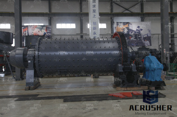
what are the step involve in cutting gear in milling machine manufacturer Grasping strong production capability, advanced research strength and excellent service, Shanghai what are the step involve in cutting gear in milling machine supplier create the value and bring values to all of customers.
 WhatsApp)
a) Gear Milling: This is one of the initial and best known and metal removal process for making gears. This method requires the usage of a milling machine. It is also to be noted that this method can produce nearly all types of gears. The method involves the use of a form cutter, which is passed through the gear blank to create the tooth gap.
After plotting the next step in milling would be HD , (I find it at the big box store "ular" 5 for a 1/4 sheet), this material holds amazing tolerances, mills very well, and will not destroy your machine when you make a mistake. If you are new this should always be the material you make a first test cut in, then on to test cuts in ...
Gear Cutting Methods : 19 Methods Of Manufacturing Of all types of Gears. Helical gear cutting on Milling Machine AIM: To make a helical gear from a CI blank using milling machine. MATERIAL REQUIRED : Cast iron blank of Ф50 mm. TOOLS REQUIRED : 1. Turning tool 2. Milling cutter ( 2 mm module ) 3. Vernier caliper ( 0 150 mm) 4. Drilling tool ...
Making a spur gear – step by step example. This is an example of making a spur gear. It is done step by step. The gear to be made has 35 teeth. The size of the teeth is 1 MOD. For a 1 mod gear the pitch circle diameter, pcd is the number of teeth in mm. The outside diameter, od .
Tslot milling cutters are identified by the TSlot bolt diameter and remanufactured with the proper diameter and width to cut the head space to the dimensions given in Table 86 in Appendix A. Position the Tslot milling cutter over the edge of the workpiece and align it with the previously cut groove.
End milling An end mill makes either peripheral or slot cuts, determined by the stepover distance, across the workpiece in order to machine a specified feature, such as a profile, slot, pocket, or even a complex surface depth of the feature may be machined in a single pass or may be reached by machining at a smaller axial depth of cut and making multiple passes.
Drawing a Gear in Sketchup. First, go up to the menu bar and click draw. Assuming you have the Involute Gear Plugin installed, there will be two options for drawing gears: Involute Gear and Key Involute Gear. We''ll look at Involute Gear first. Involute Gear. After you click Involute Gear, this window pops up.
Milling is a cutting process that uses a milling cutter to remove material from the surface of a work piece. The milling cutter is a rotary cutting tool, often with multiple cutting opposed to drilling, where the tool is advanced along its rotation axis, the cutter in milling is usually moved perpendicular to its axis so that cutting occurs on the circumference of the cutter.
Cutting speed. Cutting speed may be defined as the rate at the workpiece surface, irrespective of the machining operation used. A cutting speed for mild steel of 100 ft/min is the same whether it is the speed of the cutter passing over the workpiece, such as in a turning operation, or the speed of the cutter moving past a workpiece, such as in a milling operation.
Aug 28, 2015· I say "pretty much" because cutting a helical gear may involve some additional geometric interference between the cutter (especially if it''s large diameter) and the tooth helix that doesn''t exist in the case of spur gears. ... By far the clearest step by step explanation of cutting helical gears on a milling machine using gear milling cutters ...
CUTTING SPIRALS. Spirals that are most commonly cut on milling machines embrace spiral gears, spiral mills, counterbores, and twist drills. Worms are also cut with the aid of a vertical spindle or universal milling attachment. Examples of some of these classes of work are shown in this chapter, and in operations in chapters VIII and IX.
Hobbing is a gear manufacturing process in which gear teeth are generated through a series of cuts with a helical cutting tool. The hob and gear blank are rotated continuously until all teeth are cut. Hobbing is only possible for external gears. Gear hobbing advantages. Reduced total cost per gear wheel compared to HSS tools; High cutting speeds
6. For giving depth of cut, the table is raised till the periphery of the gear blank just touches the cutter. 7. The micrometer dial of vertical feed screw is set to zero in this position. 8. Then the table is raised further to give the required depth of cut. 9. The machine is started and feed is given to the table to cut .
When gear cutting this determines the number of teeth to be cut. see "dividing head – dividing the circle" For a truly comprehensive explanation of gears the reader is referred to "Gears and Gear Cutting" by Ivan Law. This leaves one more choice. This is whether a horizontal or a vertical milling machine .
Grinding relief (finish milled) in the root area to prevent a step in the active profile (see Figure 4) may be done with gear milling cutters as well. As the hobbing process produces a more pronounced undercut as the number of gear teeth goes down and the pitch circle diameter decreases, the crosssectional area of the root gets thinner (see ...
Milling Spur Gear on Milling Machine The gear blank is mounted on a mandrel which is supported between the center of the dividing head and one more center at the other end, as shown in fig. At a time one tooth space is cut by the milling cutter, and a dividing head is used to index the job to the next required tooth space.
38 Straight bevel gears cutting METHODS: • form milling –using a cutter (with the same form as the tooth face) and creating first one, than the opposite face flank of the tooth • involutegenerating milling–using two cutters representing one tooth of a rack and a generating process for creating a tooth profile • shaping –using a shaping rack tool and a
Also known as involute gear cutters, these tools work with a milling machine to create 14½° pressure angle spur gears. If worn, they can be sharpened and used again. To select a gear cutter, follow these steps: 1. Determine the pitch of the gear you''re cutting. Gear pitch = (No. of Teeth + 2) / OD. Round to the nearest whole number. 2.
milling method. The steps are usually machined on a horizontal milling machine with a threeedge cutter or a face milling cutter or an end mill on a metal vertical milling machine. (1) With three blade cutter milling steps. Threesided cutter has two kinds of straight teeth and wrong teeth.
Oct 09, 2018· The gear cutting operation is performed in a milling machine by using a formrelieved cutter. The cutter may be a cylindrical type or end mill type. The cutter profile fits exactly with the tooth space of the gear.
In form milling, the cutter called a form cutter travels axially along the length of the gear tooth at the appropriate depth to produce the gear tooth. After each tooth is cut, the cutter is withdrawn, the gear blank is rotated, and the cutter proceeds to cut another tooth. The process continues until all teeth are cut Broaching. Broaching can ...
Full text of "Gearcutting machinery, comprising a complete review of contemporary American and European practice, together with a logical classification and explanation of the principles involved.
Gear cutting attachment is another name applied to an indexing fixture; in this case, one that is primarily intended for cutting gears on the milling machine. HIGHSPEED MILLING ATTACHMENT The rate of spindle speed of the milling machine may be increased from 1 1/2 to 6 times by using the highspeed milling attachment.
Jul 18, 2019· Can you cut involute gears on a metal shaper machine? This video will show the process and setup involved in cutting an involute spur gear with a simple straight sided cutting .
WhatsApp)